A-9060SM2
9000M2 Series Amplifier
A-9060SM2
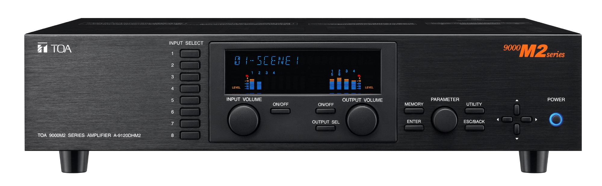
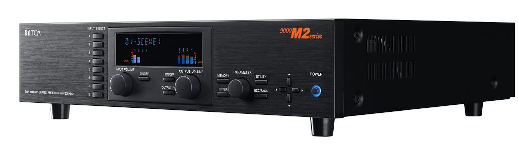
The A-9060SM2 Amplifier is designed to be used in conjunction with optional modules and can be configured for up to 8 inputs and 8 outputs. 9000 series modules as well as existing 900 series input modules can be used. The most appropriate modules can be selected depending on applications. Since it comes with one 60 W power amplifier, it can individually perform multi-origin broadcasts. It is equipped with signal processing and control functions necessary for sound reinforcement, permitting all parameters to be set at the mixer. Settings data can be stored inside the unit and called up using the keys on the front panel.
- Flexible modular design - up to 8 mic/line inputs and 8 total outputs
- Intuitive GUI software
- RS-232 control for 3rd party control systems
- EQ presets for 30 TOA loudspeakers included
- Accepts TOA ZM series remote controls (RC-001T may be required)
- 32 scene memories and 32 paging memories
- Up to 12 filters plus compressor available for each input and output channel
(*1) 0 dB = 1 V
Power Source
120 V AC, 60 Hz
Power Consumption
100 W
Rated Output
60 W
Audio Input
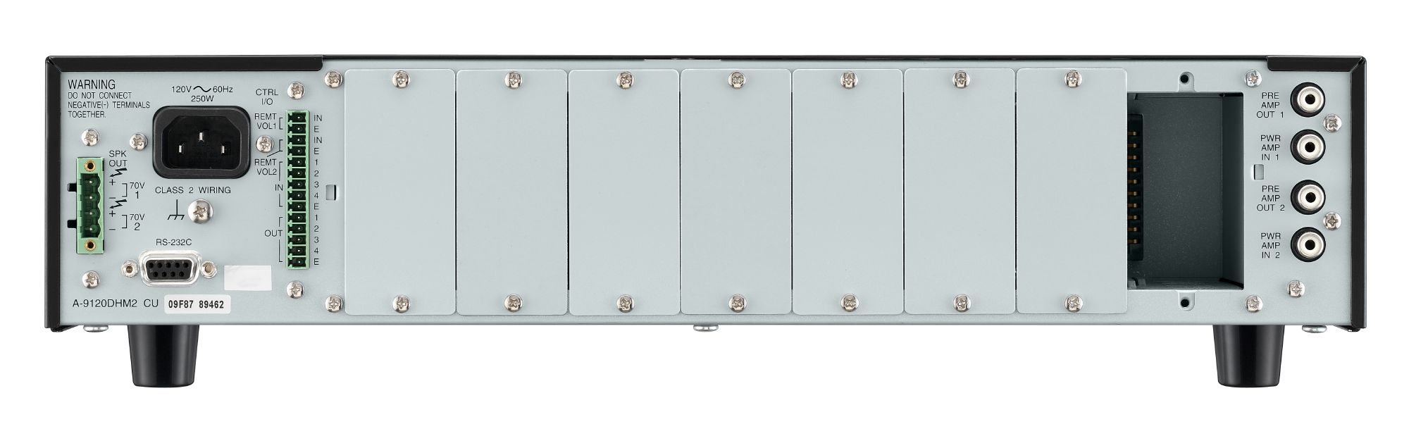
Max. 8 channels, modular construction (modules optional)
Power amplifier input: 0 dB(*1), 10 kΩ, RCA pin jack
Power amplifier input: 0 dB(*1), 10 kΩ, RCA pin jack
Audio Output
Preamplifier output 1: 0 dB(*1), 300 Ω, unbalanced, RCA pin jack
Preamplifier output 2: 0 dB(*1), 600 Ω, balanced, removable terminal block (3 pins)
Speaker output: Removable terminal block (7 pins)
(Direct) 60 W, 4 Ω, unbalanced
(Transformer) 60 W, 8 Ω/25 V/70 V, balanced
Preamplifier output 2: 0 dB(*1), 600 Ω, balanced, removable terminal block (3 pins)
Speaker output: Removable terminal block (7 pins)
(Direct) 60 W, 4 Ω, unbalanced
(Transformer) 60 W, 8 Ω/25 V/70 V, balanced
Module Slot
Analog input (slot 1 - 8): -10 dB(*1), 10 kΩ, unbalanced
Digital input (slot 1 - 4): 24 bit/48 kHz
MIX output (slot 1 - 8): -14 dB(*1), 330 Ω (CH 1 prefader output), unbalanced
Digital output (slot 5 - 7): 24 bit/48 kHz
Power supply (slot 1 - 8): +24 V, -24 V, +6 V DC
Digital input (slot 1 - 4): 24 bit/48 kHz
MIX output (slot 1 - 8): -14 dB(*1), 330 Ω (CH 1 prefader output), unbalanced
Digital output (slot 5 - 7): 24 bit/48 kHz
Power supply (slot 1 - 8): +24 V, -24 V, +6 V DC
Digital Audio Signal Reference Level
-20 dBFS
Power Bandwidth
(Direct) 20 Hz - 20 kHz, 0.02 % THD
(Transformer) 50 Hz - 20 kHz, 0.5 % THD
(Transformer) 50 Hz - 20 kHz, 0.5 % THD
Frequency Response
Power amplifier section: 20 Hz - 20 kHz, +0, -1 dB
Analog input module to speaker output: 20 Hz - 20 kHz, +1, -3 dB
Analog input module to speaker output: 20 Hz - 20 kHz, +1, -3 dB
Total Harmonic Distortion
Power amplifier section: 0.008 % (22 kHz LPF, 1 kHz, rated power)
Analog input module to speaker output: 0.01 % (A-Weighted, 1 kHz, rated power)
Analog input module to speaker output: 0.01 % (A-Weighted, 1 kHz, rated power)
Signal to Noise Ratio
At Input short, A-Weighted
, set to ALL FLAT or OFF setting
Output volume min.: 90 dB (preamplifier output)
Output volume max.: 61 dB
(preamplifier output, Input 1 volume: 0 dB, Other Inputs: OFF)
Power amplifier section: 110 dB
Output volume min.: 90 dB (preamplifier output)
Output volume max.: 61 dB
(preamplifier output, Input 1 volume: 0 dB, Other Inputs: OFF)
Power amplifier section: 110 dB
Crosstalk
-64 dB or less (at 20 kHz)
Tone Control
Bass: ±12 dB (at 100 Hz)
Treble: ±12 dB (at 10 kHz)
Treble: ±12 dB (at 10 kHz)
Parametric Equalizer
10 bands, Frequency: 20 Hz - 20 kHz, 31 points, Variable range: ±12 dB, Q: 0.3 - 5
Speaker Equalizer
10 (setup software has 30 TOA speaker presets)
High-Pass Filter
-12 dB/oct, Variable frequency range: 20 Hz - 20 kHz, 31 points
Low-pass Filter
-12 dB/oct, Variable frequency range: 20 Hz - 20 kHz, 31 points
Compressor
Depth: 1 - 5
Delay
0 - 40 ms (1 ms steps), maximum 40 ms (CH 1 + CH 2), mixer mode only
Scene/Event Memory
32
Auxiliary Function
Key lock function
Control Input/Output
RS-232C(*2), D-sub connector (9 P, female)
Control input: 4 inputs, no-voltage make contact input, open voltage: 3.3 V DC,
short-circuit current: 1 mA or less, removable terminal block (14 pins)
Control output: 4 outputs, open collector output, withstand voltage: 27 V DC,
control current: 50 mA, removable terminal block (14 pins)
Remote volume: 2 channels, connect a 10 kΩ/linear taper variable resistor or
input the DC voltage of 0 to +10 V, removable terminal block (14 pins)
Operating Temperature
-10 °C to +40 °C (14 °F to 104 °F)
Operating Humidity
35 % to 80 %RH (no condensation)
Finish
Panel: Aluminum, hair-line, black
Case: Surface-treated steel plate, black, paint
Case: Surface-treated steel plate, black, paint
Dimensions
420 (W) x 107.6 (H) x 355 (D) mm (16.54" x 4.24" x 13.98")
Weight
11 kg (24.25 lb)
Included Accessories
Power cord (2 m (6.56 ft) …1, Rack mounting bracket …2, Bracket mounting screw …4,
Blank panel …7, Blank panel mounting screw …14,
Removable terminal plug (3 pins) …1, Removable terminal plug (7 pins) …1,
Removable terminal plug (14 pins) …1, CD …1
Blank panel …7, Blank panel mounting screw …14,
Removable terminal plug (3 pins) …1, Removable terminal plug (7 pins) …1,
Removable terminal plug (14 pins) …1, CD …1
(*2) Allowing it to be controlled by a control system such as AMX and Crestron through RS-232C port.
Notes: AMX is a trademark of AMX Corporation.
Crestron is a trademark of Crestron Electronics, Inc.
Notes: AMX is a trademark of AMX Corporation.
Crestron is a trademark of Crestron Electronics, Inc.
Please download Datasheet to access full specifications.
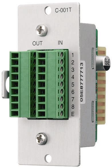
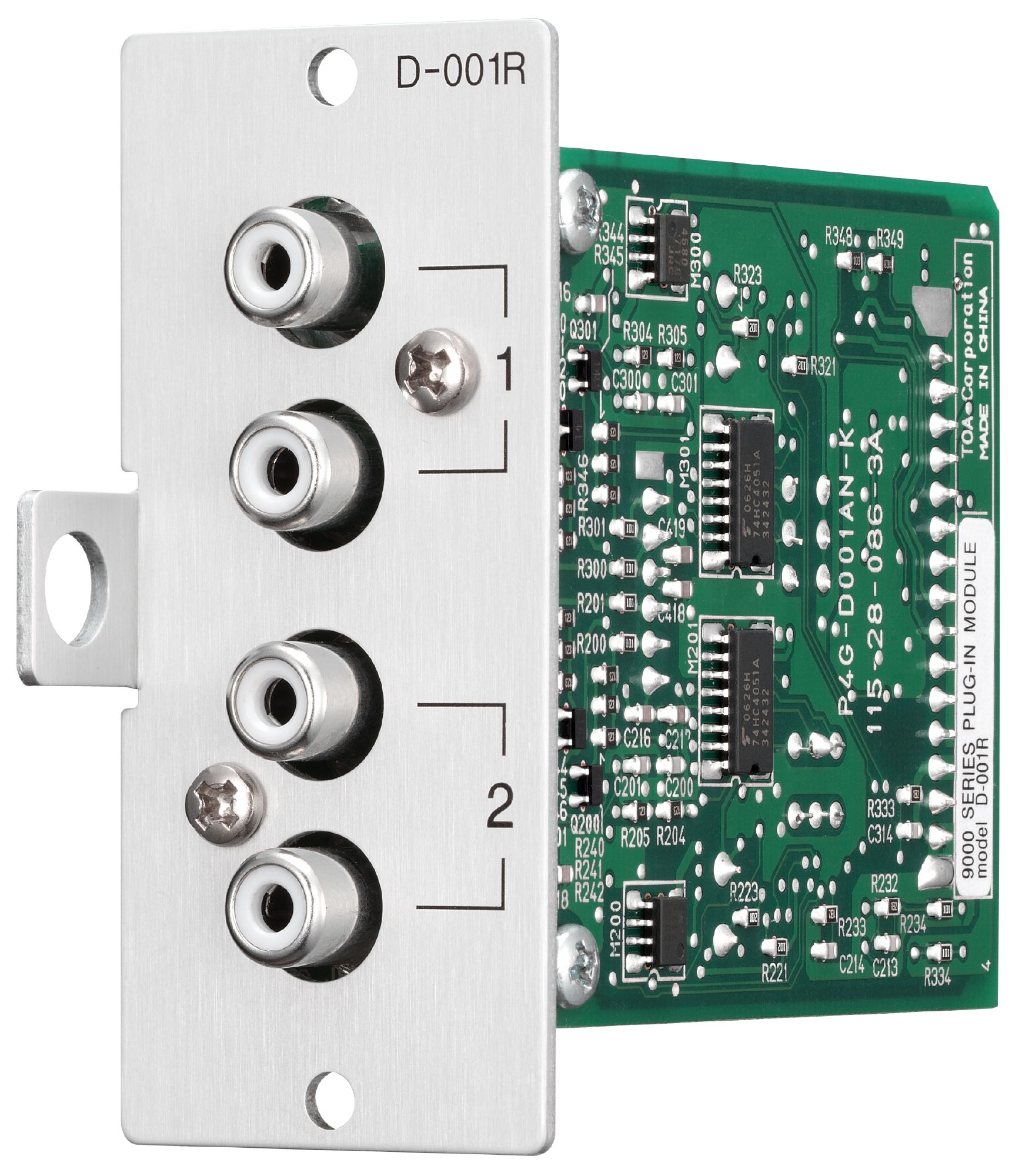
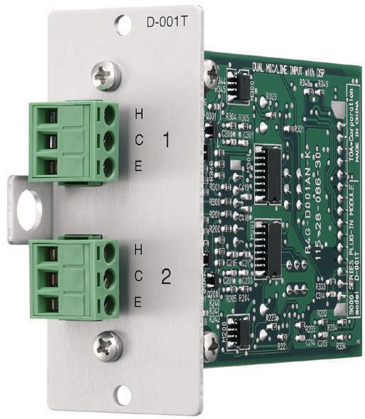
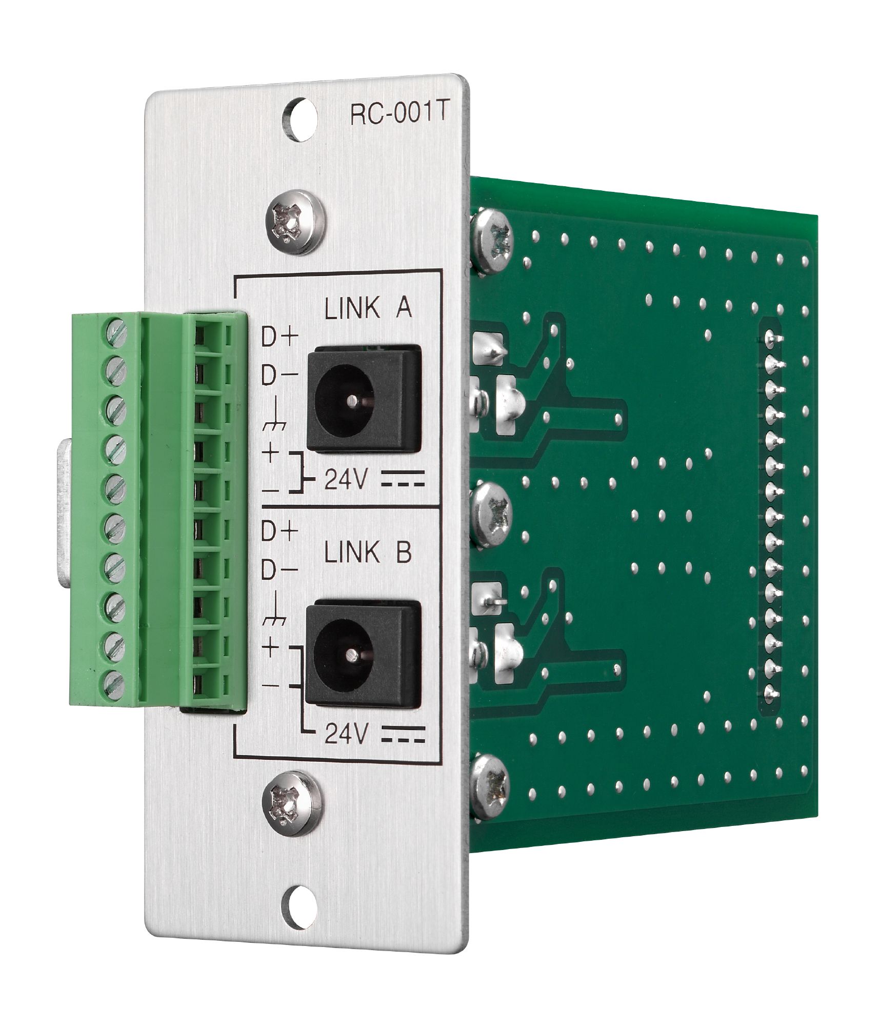
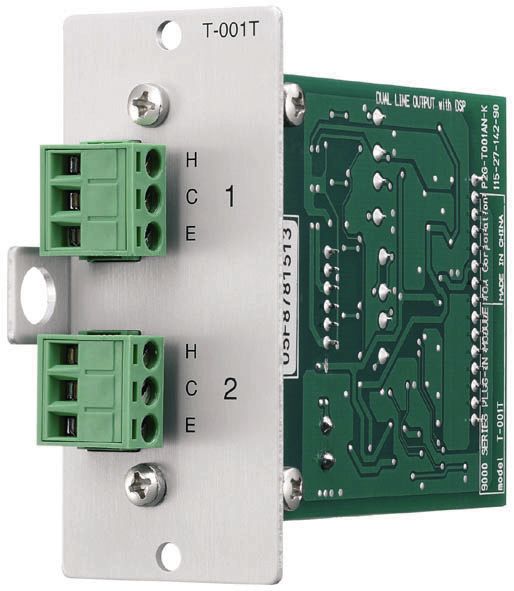
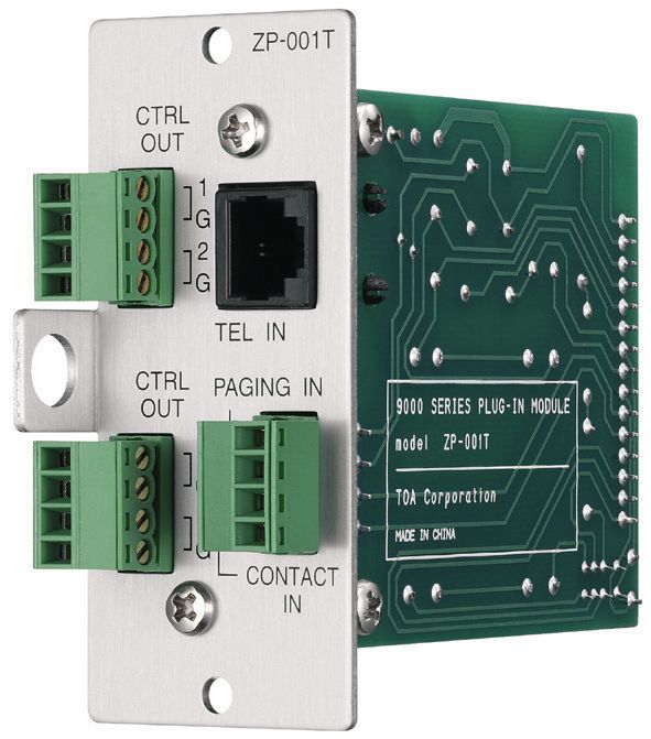
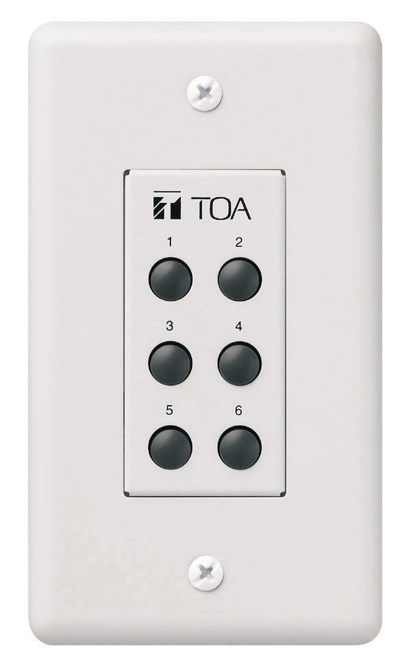
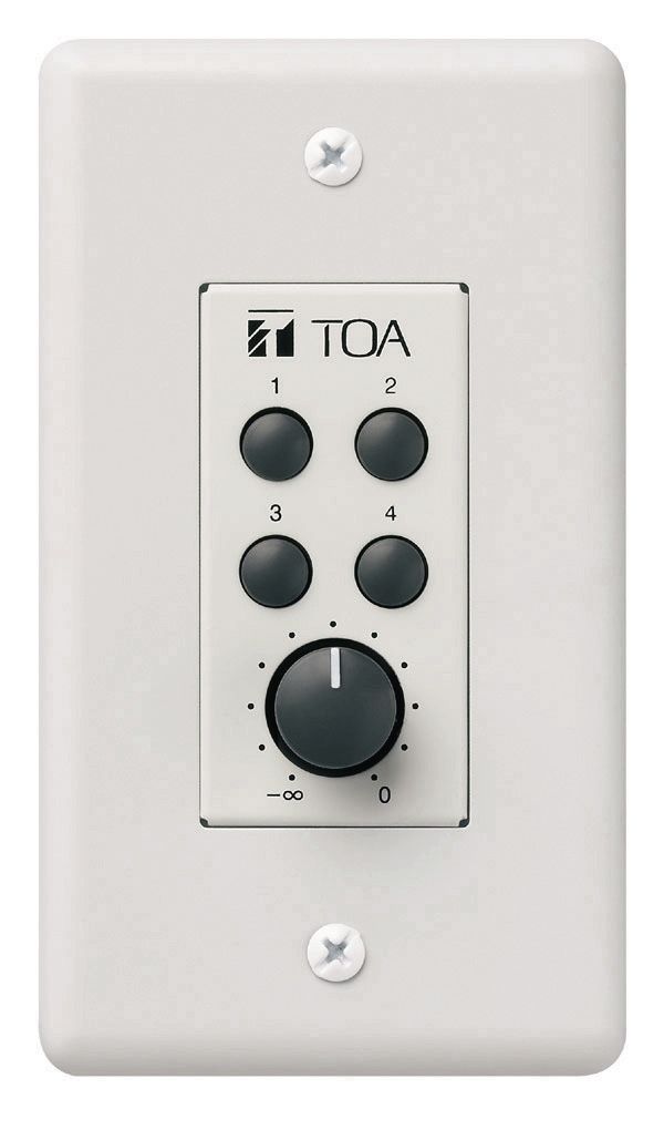
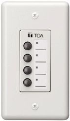
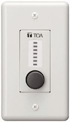
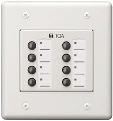
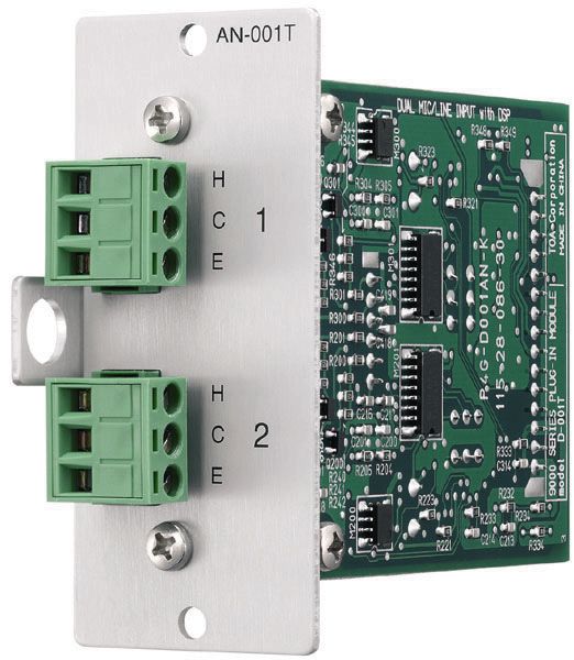
A-9060SM2 The digital mixer/amplifier shall use digital signal processing for all mixing and signal processing functions and shall be modular for flexibility in system configuration. The mixer shall comply with the limits for a Class A computing device pursuant to FCC Part 15, Subject J. The mixer shall have a frequency response from 20 Hz to 20 kHz, 3 dB. The digital mixer/amplifier shall utilize a modular architecture and be capable of up to eight input channels and eight output channels. Eight module ports shall be provided. Module ports shall include four digital input ports and three digital output ports. Each digital input port shall accept two input channels and each digital output port shall provide up to two output channels. All eight module ports shall accept analog input modules and shall support control I/O function modules and analog output modules. The mixer shall have eight independent mixing busses. A patching loop with line output connections for mix buss 1 and associated power amplifier inputs shall be provided on the rear panel. A Transformer-less Balanced Line Output shall be provided for Mixing Buss Two on the rear panel. Buss outputs 1 and 2 shall also include digital signal processing which will support paging event-based [or scene-based] programming of the following settings: high and low pass filters, 10-band parametric equalization, compression, bass and treble, delay, loudness compensation, and pre-programmed speaker equalization settings. The front panel shall be equipped with controls for full adjustment of menu settings and parameters without the need for a computer. There shall be controls for input & output channel selection, along with a corresponding level adjust knob and channel on/off function. The front panel shall also include a fluorescent back-lit display, which will provide metering for input/output levels, parameter values and system status. The display shall be equipped with a time-out function, which activates after 30 seconds if no controls are adjusted and can be deactivated by adjusting any front-panel control. All software-based settings shall be accessible from the front panel controls. Thirty-two FLASH memory presets shall be available to store scene data and an additional thirty-two memory presets shall be available to store paging events. These memory sets shall both be contained in a program template which can be uploaded from or stored to a Windows PC. Programming of the mixer input/output routing and digital processor settings shall be stored in each scene preset. Each input channel shall support paging-based programming of the following settings: channel priority, ducking on/off status, ducking depth, input to output routing, output level and remote contact activation. Up to 3 priority levels shall be available. Inputs assigned to the same priority level shall operate according to one of three selectable logic rules: First in/first out (FIFO); Last in/first out (LIFO); or mixing. It shall be possible to recall any scene memory and paging event memories simultaneously and they shall operate independently from each other with regard to recall, input/output level, input settings and cross-point routing assignments. Input channels equipped with the D-001T input module shall support paging event-based [or scene-based] programming of the following settings: channel priority, ducking on/off status, ducking depth, input to output routing, remote contact activation, VOX trigger threshold, high and low pass filters, 10-band parametric equalization, compression, bass and treble, and loudness compensation. Each built-in output channel and each output channel equipped with a T-001T output module shall support paging event-based [or scene-based] programming of the following settings: high and low pass filters, 10-band parametric equalization, compression, bass and treble, delay, loudness compensation, and pre-programmed speaker equalization settings. A power off mode setting shall allow selection of whether input and output volume settings revert to pre-programmed default levels or retain the last used setting after the power is turned off and back on. A power on mode setting shall allow selection of whether to revert to the last used preset scene at power on, and if not, which preset scene is to be active at power on. Security features shall include a key-lock setting to selectively disable user changes to input, output, and/or utility settings. Input and output channels shall be selectable for user lock-out on an individual channel-by-channel basis. Password protection of the lock-out settings shall be available by the use of a user-selected password. The digital mixer/amplifier shall have a built-in RS-232 port for connection to a Windows-based computer for storage and retrieval of setup information and for connection to third-party ASCII-based serial control systems. Software to enable PC-based data storage and retrieval shall be provided free of charge. Stored information shall include all software-based settings. The RS-232 port and software shall also provide for future FLASH upgrades of the software-based feature set. Four control contact inputs shall allow event activation by remote dry contact closure. The function of each control input shall be software assignable activate Event, Volume Up/Down (Input or Output), Mute (Input or Output), Power On/Off, Paging Event, Paging Prohibit, Emergency Mute or Synch On/Off (expandable to twelve with C-001T module). The contact inputs shall also allow the use of the optional ZM-9003 (6-button) remote panel. Four open-collector control outputs shall allow triggering of external equipment based on event status. The function of each control output shall be software assignable using front panel controls. Each of two remote volume control channels shall be assignable to allow the volume of any one input or output channel to be remotely controlled using a 10k ohm linear taper potentiometer or a DC control voltage varying over the range of 0 to 10 volts. The two control channels shall also allow the use of the optional remote control panels ZM-9001 (6 button) and/or ZM-9002 (4-button, plus level control knob). An optional control module shall allow additional remote control functions using a dual RS-485 serial control bus. The module shall allow the use of up to eight assignable remote panels per bus for a total of sixteen remote panels. The remote panels may be software assigned to control the following functions. Buttons: Each remote panel button shall be programmable for scene memory change, channel cross-point assignment (in either simultaneous or exclusive priority mode), paging event activation, remote contact output activation. An LED indicator for each button shall display that button’s active status. Rotary knobs: Each remote panel knob control shall be assignable to control the level of one or more (up to eight) input or output channels. A multi-segment LED indicator for each knob shall indicate the level status the assigned channel(s). Output channel 1 shall meet or exceed the following specifications: Output power: 60 watts; recommended minimum load impedance, direct unbalanced output: 4 ohms; recommended minimum load impedance, transformer balanced output: 8, 10.4 (25 V line) or 81.7 (70.7 V line) ohms; frequency response: 20 Hz to 20 kHz (+1, -3 dB); output distortion: 0.008% THD, measured at 1 kHz at rated output power with 22 kHz low pass filter; power bandwidth at rated output (direct): 20 Hz to 20 kHz at 0.02% THD; power bandwidth at rated output (transformer): 50 Hz to 20 kHz at 0.5% THD; output connector: 7-pin removable terminal block. Output channel 2 shall be transformer isolated and shall meet or exceed the following specifications: Output impedance: 600 ohms, balanced; output level: 0dBV nominal, where 0dBV = 1 volt; frequency response: 20 Hz to 20 kHz (+1, -3 dB); output distortion: 0.008%, measured at 1 kHz at 0dBV output (where 0dBV = 1 volt) with 22 kHz low pass filter; output connector: 3-pin removable terminal block. The unit shall include a kit for mounting in an RIAA 19†rack and shall be equipped with an IEC standard grounded AC receptacle. Dimensions (W x H x D) shall be 16.54†x 4.24†(3.5†w/out feet) x 14†(420 x 107.6 x 355 mm) and weight shall be 24.25 lbs. (11 kg). The digital mixer/amplifier shall be TOA model A-9060SM2. The two channel 24-bit mic/line module shall be TOA model D-001T. The two channel 24-bit unbalanced RCA line module shall be TOA model D-001R. The two channel 24-bit output module shall be TOA model T-001T. The 8-in/8-out I/O control module shall be TOA model C-001T The RS-485 Remote-control bus module shall be called the RC-001T. The telephone access zone paging module shall be TOA model ZP-001T. The ambient noise controller module shall be TOA model AN-001T. The ambient noise sensing microphone shall be TOA model AN-9001. The 6-button remote panel shall be TOA model ZM-9001. The 4-button, single potentiometer remote panel shall be TOA model ZM-9002 The 4-button, RS-485 remote panel w/LED indicators shall be TOA model ZM-9011. The single rotary knob, RS-485 remote panel w/LED indicators shall be TOA model ZM-9012. The 8-button, RS-485 remote panel w/LED indicators shall be TOA model ZM-9013. The 4-button, plus single rotary knob RS-485 remote panel w/LED indicators shall be TOA model ZM-9014.


Need other technical materials like software, firmware, or EASE files? Please visit our Download Center.
*Sign-in or membership registration is required.
Get Your Quote.
- Products
A-9060SM2